Background
CrackMe Name: KataVM – Level 1
CrackMe Author: Towel
CrackMe Description:
A small challenge with a virtualized function. It is not designed to be overly difficult.
Instead, it is designed to give you something simple to practice on.
No fancy dynamic obfuscations or static analysis protections—just the VM.
There is no flag, just working input and non-working input.
Your task is to find input that gives you the success message.
Execution
After executing the file, a banner and prompt for input are printed. When entering a random string for input the, a negative message is printed.
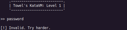
At this phase, nothing is known about the internals of the challenge. In an ideal world, we would be able to locate the negative and positive messages, assuming no obfuscation is applied to the strings. Calls to library functions to print to standard out and read from standard in may also prove to be useful, but little more can be done without reverse engineering.
Reverse Engineering the Host Executable
Knowing that this code is virtualized, Ghidra was used to reverse engineer the host executable and to write a custom processor for the KataVM instruction set.
Find the Virtual Machine
The description provided for this challenge indicated that there are no static analysis protections, which makes getting started on the reverse engineering process very easy.
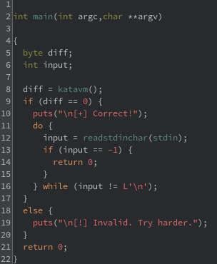
After loading the binary into a Ghidra project, a main function is immediately found at address 0x101170. This is a simple function that checks the return value of a function call. If the return value is equal to 0, then the good output of [+] Correct! is printed. The function can be thought of as something like strcmp, where a value of 0 is equal and usually desired. However, we will be calling this function katavm moving forward.
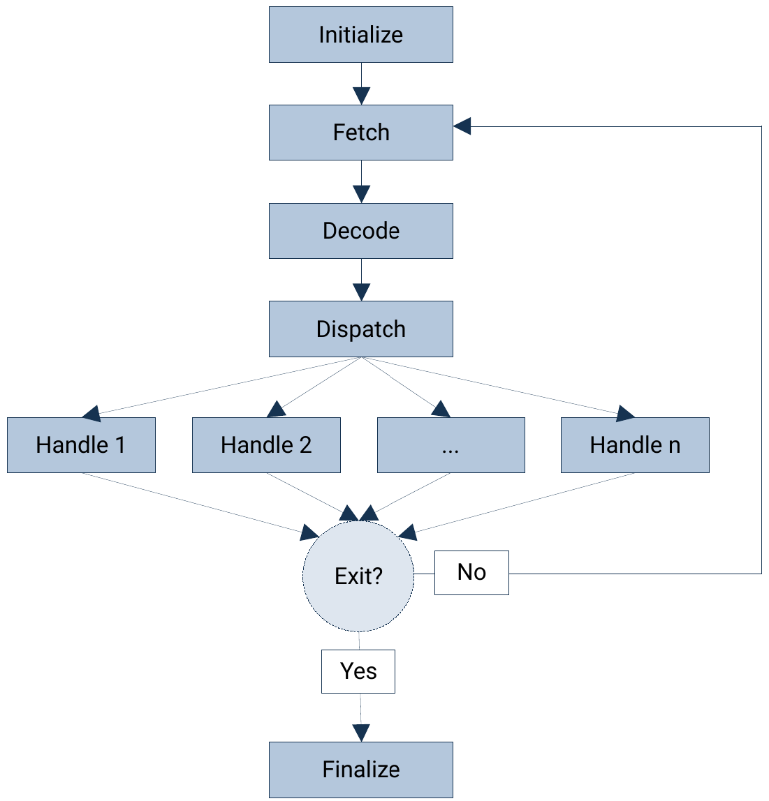
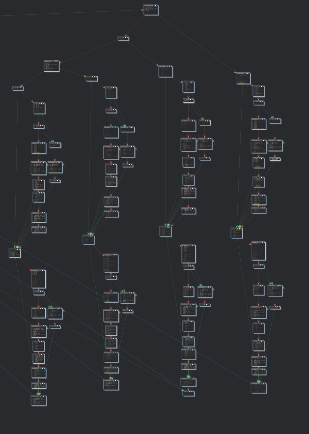
Looking at the control flow graph (CFG) of the katavm function, it can be seen that it follows the structure that one would expect from a virtual machine (VM) that runs virtualized code. In general, there will be some form of initialization, including loading of code and setting up default register values. Then the most basic VM will fetch the first instruction, decode it, and dispatch it to a handler. This repeats with the next instructions until one of the handlers directs the VM to exit.
Initialize
The first action of note in katavm is the allocation of a large stack frame, approximately 12KB. The frame is then populated with bytes using memcpy. Ghidra recognizes the copy source as a different segment. Furthermore, the bytes that are loaded are seen to have a high entropy. This usually indicates an unpacking process, but the entropy is not high enough to be a standard compression algorithm nor encryption algorithm. It is not immediately clear what the format of the loaded section is, but the sheer size is a good indicator that it is virtual machine code. After copying, the address of the first byte is stored in RDX.
Next, the 32 bytes on the top of the stack are set to zero using xmm0. This is not an unusual thing to see when initializing numerous local variable to 0, even in non-obfuscated functions. It is later discovered that this is setting the initial values of the virtual registers to 0.
Fetch
Looking at the function CFG, the next basic block is seen to have many incoming jumps. This is a good indicator that the basic block is the beginning of the processing loop, thus should fetch the instructions.
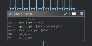
The instructions in this block perform three actions:
- Read eight bytes from [RDX + 0x01] into a local variable at [RSP + 0x20].
- Read one zero-extended byte from [RDX] into EAX, effectively AL.
- Compare AL to 0xAA to make a conditional jump.
There is no reason to believe (1) is important at this stage, but (2) and (3) reveal useful information. Assuming the check for (3) is used to match an opcode to a handler, that would indicate that RDX is effectively the virtual instruction pointer (VIP). It can be assumed at this point that all instructions are eight bytes long, but this is disproven as analysis continues. As a side note, the fact that these bytes are being read directly indicates that they are not going to be decompressed or decrypted. The high entropy is simply an artifact of the instruction set.
Decode
With the instruction fetched, it must be decoded. There was a small taste of that in the fetching step, but more opcodes are assumed to exist. There is light obfuscation in this step, but nothing that cannot be statically reverse engineered. For example, not all tests for the opcode are for equality; some tests check if the opcode is greater than or less than a magic number. Nevertheless, following all execution paths indicates that the following opcodes exist in the instruction set:
| Opcode | Dispatch Address |
|---|---|
| 1E | 101410 |
| 3E | 101BA8 |
| 4A | 101379 |
| 5D | 101B40 |
| 7C | 101B08 |
| 8B | 1014C0 |
| AA | 101470 |
| D5 | 101810 |
| B1 | 101A50 |
| C3 | 101504 |
| EF | 101A90 |
| F6 | 1013CE |
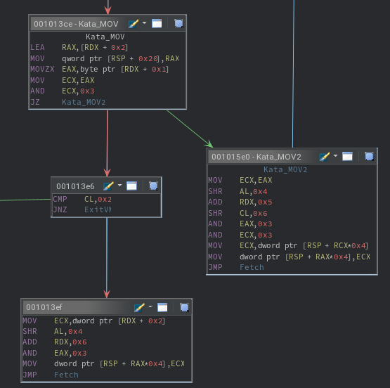
The term “dispatch address” is a misnomer here, since further decoding takes place for each instruction. This decoding takes place on the second byte in the instruction, hereby referred to as the subcode. The following steps are performed after taking any branch for any valid opcode:
- Read eight bytes from [RDX + 0x02] into a local variable at [RSP + 0x20].
- Read one zero-extended byte from [RDX + 0x01] into EAX, effectively AL.
- Copy EAX to ECX.
The byte stored in AL (and CL) is the subcode. At a high level, the following pseudo-code describes one way the subcode is decoded, while the other way also includes branches for when x is equal to 1 or 3:
byte s := subcode & 3
if(s = 0) then
    <do variation 1>
else if(s = 2) then
    <do variation 2>
For the first virtual machine instruction, the variation 2 branch is taken. If all operations of this branch are smashed into one line, the following ugly assignment is created: [RSP + ((subcode » 4) & 3) * 4] = (dword) [RDX + 0x02]. This is a very important piece of the puzzle. At a higher level, it can be understood by breaking it down into pieces again:
- (subcode » 4) & 3 provides a number in the range [0, 3]; call this value X.
- (dword) [RDX + 0x02] indicates that a dword will be written.
- [RSP + X * 4] is an offset in the stack if the first four values are dwords.
Therefore, it can be concluded that the first four values on the stack are 32-bit virtual registers for the VM. More importantly, any time a similar computation appears, it can be simplified to “virtual register X.”
Regarding variation 1, a similar ugly assignment can be created:
[RSP + ((subcode » 4) & 3) * 4] = [RSP + ((subcode » 6) & 3) * 4]
The left-hand side (LHS) of this assignment is identical to variation 2, while the right-hand (RHS) side is different. However, the RHS is similar to the LHS, indicating that the source value comes from a virtual register, which can be called Y.
This allows for a more useful pseudo-code representation:
byte x := subcode & 3
dword dst := vreg_X
dword src
if(s = 0) then
    src := vreg_Y
else if(s = 2) then
    src := immediate
OPERATE_ON(dst, src)
The subcode decoding process for cases when there are four branches uses similar logic to decode virtual registers and immediate values, thus will not be explained for the sake of brevity.
Dispatch
The process to dispatch is intertwined with decoding for this VM. The only additional responsibility of dispatching is to update the VIP to the next instruction. The assumption from the fetch step that all instructions are 8 bytes long is disproved here. After decoding the opcode and subcode, there is an update to EDX (the VIP). This update is not the same for all branches, meaning the instructions have variable lengths.
Similar to the process to discover all opcodes, it is possible to discover all instruction lengths for the instruction set, allowing an updated table with accurate dispatch addresses. The exhaustive list of instruction lengths is described in the conclusion.
Handle
The last step of reverse engineering the host is to understand the purpose of each opcode and subcode. It has already been discovered that the subcode simply chooses the data to work with, but the operations that are performed for each opcode are unknown.
The handlers for the opcodes are largely not obfuscated. Of the 12 opcodes, handlers for 7 of them have nearly identical code, with the only difference being one instruction. For example, take the previously discussed copying instruction:
[RSP + ((subcode » 4) & 3) * 4] = (dword) [RDX + 0x02]
To instead perform in-place addition (as is the case for opcode AA), the following instruction is executed:
[RSP + ((subcode » 4) & 3) * 4] += (dword) [RDX + 0x02]
This level of similarity makes it trivial to reverse engineer handlers that are related to mathematical and bitwise operations. These trivial opcodes are 3E, 4A, 7C, 8B, AA, B1, and EF.
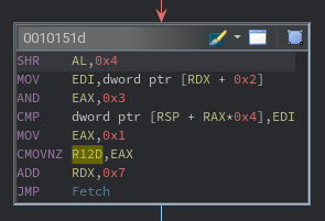
However, five opcodes remain that do not follow the template. While different, the handler for opcode C3 is somewhat similar. The same two-branch subcode variants are seen, but there is no arithmetic that occurs. Instead, a comparison is made, whose result is stored in the host’s R12 register. If there is ever a difference in the operands, 1 will be stored for the current and all future comparisons. Intuitively, this is the ultimate return value of katavm.
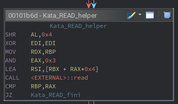
For two of the remaining opcodes, the purpose is easy to ascertain by looking for calls to external functions. For opcode 5D, a call to read() is made. Likewise, a call to write() is made for opcode F6. The exact arguments for each call are calculated using the same subcode technique as other instructions.
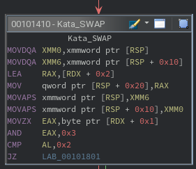
That leaves two opcodes, starting with 1E, which introduces some complexity. By using the xmm0 and xmm6 registers, the first 16 bytes of the stack are swapped with the next 16 bytes of the stack. Back in the initialize step, the first 32 bytes on the stack were set to zero. This indicates that the number of registers should be eight, not the working assumption of four. That would mean that the 1E opcode can be thought of as swapping the normal registers with standby registers, where only the normal registers can be accessed by other instructions. As for the subcode, it is only used to decide the instruction length.
That leaves opcode D5, which occupies a large majority of the CFG for the katavm function. This handler was not reverse engineered statically due to its four large branches of very similar code. Instread, a debugger was used to watch how the instruction parameters were used to transform the virtual registers. In doing so, it can be observed that the D5 opcode is used to rotate the registers left or right, including the standby registers. The actual values remain unchanged, only the register containing the value is changed.
Final Instruction Set
The final table to describe the KataVM instruction set can now be created.
| Purpose | Opcode | Subcode Case | Dispatch Address | Instruction Length (Bytes) |
| SWAP | 1E | |||
| 0 | 101444 | 5 | ||
| 1 | 101444 | 6 | ||
| 2 | 101801 | 9 | ||
| 3 | 102179 | 10 | ||
| OR | 3E | |||
| 0 | 101C00 | 4 | ||
| 2 | 101BC5 | 7 | ||
| ADD | 4A | |||
| 0 | 1015C0 | 2 | ||
| 2 | 10139B | 7 | ||
| READ | 5D | |||
| 0 | 101C60 | 3 | ||
| 2 | 101B61 | 8 | ||
| SHL | 7C | |||
| 0 | 101C20 | 4 | ||
| 2 | 101B29 | 7 | ||
| XOR | 8B | |||
| 0 | 1015A0 | 3 | ||
| 2 | 1014DD | 6 | ||
| SUB | 8B | |||
| 0 | 101C40 | 3 | ||
| 2 | 101491 | 8 | ||
| ROT | D5 | |||
| 0 | 101860 | 4 | ||
| 1 | 101F58 | 3 | ||
| 2 | 101CD0 | 5 | ||
| 3 | 101600 | 9 | ||
| SHR | B1 | |||
| 0 | 101BE0 | 2 | ||
| 2 | 101A71 | 6 | ||
| CMP | C3 | |||
| 0 | 101570 | 4 | ||
| 2 | 10151D | 7 | ||
| WRITE | EF | |||
| 0 | 101ABD | 2 | ||
| 1 | 102180 | 4 | ||
| 2 | 101F00 | 3 | ||
| 3 | 101CA0 | 5 | ||
| MOV | F6 | |||
| 0 | 1015E0 | 3 | ||
| 2 | 1013EF | 9 |
Developing a Ghidra Processor
The original plan of attack was to develop a disassembler in Python to reverse engineer virtual code. However, a text file of disassembled code is hardly useful for 15KB of code. Instead, development of a Ghidra processor was decided on, since it allows for analysis of the virtualized code using the features from the Code Browser and other tools.
Crash Course
There are two invaluable resources to get started with development of a custom Ghidra processor: existing processors and the Sleigh documentation $GHIDRA_HOME/docs/languages/html/sleigh.html.
At a minimum, the following files need to be created for any processor, where the base name will depend on the processor that is being defined:
KataVM/
├─ data/
│  ├─ languages/
│  ├─ katavm.cspec
│  ├─ katavm.ldefs
│  ├─ katavm.pspec
│  └─ katavm.slaspec
└─ Module.manifest
CSPEC
Standing for compiler specification, this file defines everything the compiler knows about the program. The vast majority of what can be defined is unnecessary for KataVM. As such the data-ptr32.cspec file was copy and pasted as the katavm.cspec file. Not everything in this file is necessary but was left in to keep Ghidra happy. For example, there is no stack, but the stack pointer must be defined.
The main focus is the default calling convention. The description of the challenge noted that there is only one function, but the output of the function must be linked to the register that is modified by the virtual CMP instruction. On the host, this is the R12 register. However, the register has been named EQ for the virtual machine. The register itself will need to be defined later.
LDEFS
Standing for language definitions, this file defines different aspects of the language such as variants in the endian or bit size. For KataVM, only a 32-bit, little endian language is defined. The bit size was chosen based on the size of the registers, while the endian is set to match the host’s endian. This may not always be the case, but yielded good results for this challenge. The specification files for each language variant must also be defined, which is easy when there is only one variant.
PSPEC
Standing for processor specification, this files defines the purpose of the registers. The program counter and all named registers should be defined here. For KataVM, a VIP register is used for the program counter. The normal registers are R0 – R3 and the standby registers are S0 – S3.
SLASPEC
Standing for SLA specification, this file contains the SLEIGH code to define the meat and potatoes for the processor. Alternatively, the body can be moved to a separate file and included, which was done for KataVM. Only the basic purpose of the file sections will be described here, since the SLEIGH documentation will prove to be sufficient for more use cases.
First, the SLEIGH code defines the endian, byte alignment, address spaces (including register spaces), and name any registers that will be used.
The virtual code has special instructions to read and write bytes. These operations are not natively supported by PCode, so custom PcodeOps are defined for read and write operations. These will appear as black box function calls in decompiled code.
Next, the bit fields for every instruction are defined. There is almost certainly a more succinct way to do this than what was done for KataVM, but optimizing code readability was chosen over optimizing code length. The bit fields include the opcode, subcode (named *_src_t), and any related operands. The length of the instructions are also defined in bits.
Lastly, the matching of instruction to instruction definition is presented. For each matched instruction, a related body defines how to modify the operands such that the instruction is executed. Technically, the body could be blank and the code would happily disassemble. However, the body is later lifted to Pcode, which enables code to be decompiled and other useful analyses to take place.
Workaround for Long Instructions
One limitation of Ghidra is that matched instructions are stored in a 64-bit native data type. In other words, an instruction cannot be longer than 64 bits. Though, there does seem to be some level of optimization at the time that the SLEIGH code is compiled, where an instruction longer than 64 bits is allowed when there is a variant of the instruction that fits within 64 bits and has the same Sleigh body.
Take the virtual SWAP instruction as an example. There are four variants, two that are longer than 64 bits and two that are not. Despite this, the body that defines how the instruction is executed is the exact same for all variants. Therefore, no problems arise.
Now consider the ROT instruction. There are four variants, one that is longer than 64 bits and three that are not. Furthermore, the body that defines how the instruction is executed is not the same for all variants. Due to this, Ghidra will throw some errors about a 72-bit instruction being too long.
To work around this, the instruction length is set to 64 instead of 72. Then, at the end of the body, an unconditional jump is made 9 bytes ahead of the current instruction. This overrides the fall through address, effectively making the instruction length 9 bytes (72 bits). The downside is that disassembly is significantly slower, since PCode needs to be reasoned with to follow the jump destinations.
Results
All definition files add up to approximately 1000 lines, thus need not be included here. Instead, take the following example of the most complex instruction: a right-rotation of normal and standby registers that uses a workaround for a 9-byte instruction:
define token insn_rot3 (64) # NOTE: This should be 72
    it3_opcode = (0,7)
    it3_src_t  = (8,9)
    it3_data   = (16,23);

:ROR cnt is it3_opcode=0xd5 & it3_src_t=3 & it3_data [cnt=8-it3_data;]
{
    local i:1 = cnt;

    <ROTATE>
    if (i==0) goto <END>;
    local tmp = S3;
    S3=S2; S2=S1; S1=S0; S0=R3;
    R3=R2; R2=R1; R1=R0; R0=tmp;
    i = i - 1;
    goto <ROTATE>;
    <END>

    local reloc:4 = inst_start+9;
    goto [reloc];
}
Having defined the KataVM processor the virtual code is extracted from the host binary and saved to its own file. That file is imported to a Ghidra project using the custom processor. Using the Code Browser, the code is (slowly) disassembled, allowing for reverse engineering of the virtual code to begin.
Reverse Engineering the Virtual Code
As hinted towards in the description, the virtual code is only one function. By looking at the decompiled code, it is trivial to determine that the beginning of the function prints the challenge banner using multiple calls to the virtual WRITE instruction.
Next, two calls to the virtual READ instruction take place, each reading 4 bytes. Since there is only one prompt for input, it can be assumed that this is just a tricky way to store one input in two virtual registers.
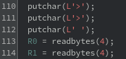
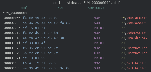
Scrolling to the bottom of the function reveals something interesting. There are four values that the return value relies on. This means there are two more calls to READ that are tucked away in the body of the function.
![]()
A close look at the decompiled code reveals one oddity in the custom processor: the CMP instruction was inverted to behave more similarly to a traditional comparison instead of something like strcmp. As a result, the return value is the inverted EQ register. From a practicality view point, this just means that EQ must be initialized as 1 at the beginning of the function. This is easy to set in the code browser and results in a return statement that is more clear.
![]()
Now it is known that there are four parts of 4-byte input that are transformed and expected to match four hard-coded values. In theory, this is simple to reverse engineer. In practice, the transformations are not intuitive and burdensome to follow.
Solution 1: Symbolic Execution
In cases with transformations that are not feasible for a human to mentally solve, satisfiability modulo theory (SMT) can prove to be useful. Building on that, symbolic execution can allow for automatic tracking of transformations of a symbolic variable, which can be solved to match a constraint using SMT.
The obvious roadblock to this is that the virtual code is running a custom instruction set. This removes the possibility Triton (and my extension, Koi), since implementing a custom instruction set would require a custom build that includes the custom instruction set. For similar reasons, Angr cannot be used. The last tool in my repertoire is the Binary Analysis Platform (BAP), which allows for a custom instruction set to be defined using a lisp to lift it to their intermediate representation, BIR. From there, any BAP analysis can be applied to binaries of that custom architecture, including symbolic execution.
However, that process should sound familiar, since it has already been performed for Ghidra. The custom instruction set has already been lifted to PCode, which is why the decompiled code is available. So, as to not duplicate work, a symbolic executor of Ghidra’s PCode is needed. A quick search reveals some attempts of similar tools, but none that are a plugin for this use case. This led to the development of a new Ghidra plugin — Ghimera.
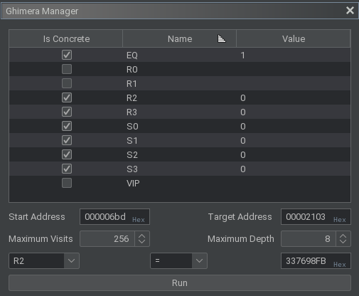
Using Ghimera, all registers can be assigned a concrete value or left as symbolic. A start address defines where to begin symbolic execution, while the target address defines when symbolic execution can end. There are also place holders for the maximum number of times to execute an instruction and maximum number of forks to allow, but these currently do not enforce the set limits. Lastly, one assertion on a register can be defined, which will be solved for at the end of symbolic execution using Z3. The plugin was not originally developed to cover all possible PCode and there is no support for forking at branch points. These nice-to-have features may be added later, but are not needed now. Simple tests were executed before defining the actual parameters, since constraint solving can be quite slow.
For the real parameters, the R0 and R1 registers are marked as symbolic, since they each store 4 bytes of user input. All other normal and standby registers were assigned the concrete value of 0, since it is known by reverse engineering the host executable that this is the initial value in those registers. The EQ pseudo-register was assigned the concrete value of 1 for reasons previously mentioned. The address to begin symbolic execution was set to the first address after the initial read statements. The target address was set to the first comparison, where a value of 0xFB987633 is expected to be stored in R2. (Since the architecture is in little endian, the bytes expected are reversed. This would be simple to automate in the plugin code, but was not considered at the time.)
The transformations from input to the expected output were gathered in less than one second using Ghimera. After which, the Z3 prover was allowed to run for 75 hours before manually being killed. While the original thought was to solve for 25% of the input at a time, a closer look at the algorithm shows that the first two quarters of input transform each other. As a result, the solving process is more complicated than original anticipated. While the solution may have come during hour 76, this is not a process that is readily accepted for reuse to solve each quarter, even if Ghimera itself is not flawed.
Solution 2: Algorithm Identification
Since the inputs transform each other through XOR operations and what initially looks like one or more keys, it was assumed that the algorithm implements a Feistel cipher. So, the list of well-defined Feistel ciphers were quickly skimmed for transformations that are found in the disassembled virtual code. Interestingly, there are only two algorithms with reference code that includes both left and right shifts: TEA and XTEA.
TEA was considered first, since it comes before XTEA alphabetically. As previously mentioned, the disassembled code performs both left shifts and right shifts, which is apparently uncommon. Furthermore, the amount that is shifted in both directions matches between the disassembled code and provided reference code. Further reverse engineering of the disassembled code continued to line up with the reference code, providing a good case of this being the encryption algorithm in use.
void tea_encrypt(uint32_t v[2], const uint32_t k[4]) {
    uint32_t v0 = v[0], v1 = v[1];
    uint32_t delta = 0x9E3779B9;
    uint32_t sum = 0;

    for(uint32_t i = 0; i < 32; i++) {
        sum += delta;
        v0 += ((v1 << 4) + k[0]) ^ (v1 + sum) ^ ((v1 >> 5) + k[1]);
        v1 += ((v0 << 4) + k[2]) ^ (v0 + sum) ^ ((v0 >> 5) + k[3]);
    }

    v[0]=v0; v[1]=v1;
}
There are several parts of this encryption algorithm that need to be recovered to perform decryption. First of all, v is understood to be the two pieces of input in R0 and R1. The value for k requires the disassembled code to be traced and tied back to the reference code. By doing so, the values are revealed to be
{ 0x80b86e21, 0xa268295d, 0xf171f22d, 0x28a13c94 }.
In the process of tracing, it was also discovered that a non-standard delta was used: 0xe09ffbb1.
![]()
![Image 16: First usage for k\[0\] and k\[1\] on v0.](/reverse-engineering/katavm-level-1/img16.png)
![]()
![Image 18: First usage of k\[2\] and k\[3\] on v1.](/reverse-engineering/katavm-level-1/img18.png)
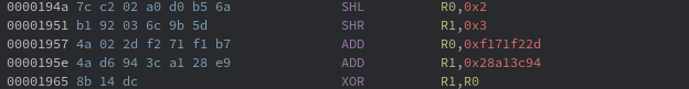
The last part to recover is the number of rounds for encryption. To do so, the disassembled code between the first pair of reads and first comparison were queried using the regular expression SHR.*0x5. This results in 63 results, which is strange since there is an even number of right shifts per round. A non-standard shift was queried using the regular expression SHR.*,0x[^5], which reveals a single right shift that shifts by three instead of five. The left shift here is also non-standard, shifting two instead of four.
There are 18 right shifts after the non-standard right shift. The fact that this is an even number (and the keys that are used) indicates that the non-standard shifts are applied to v1. Furthermore, the round number that the shift occurs can be computed to be (64 – 18) / 2 = 23. For decryption, this would be round 32 – 23 = 9. Even without these deductions, there would only be 64 possibilities to try, which is trivial to brute force. With this information determined a decryption algorithm can be developed.
void kata_decrypt(uint32_t v[2], const uint32_t k[4]) {
    uint32_t v0 = v[0], v1 = v[1];
    uint32_t delta = 0xe09ffbb1;
    uint32_t sum = delta << 5;

    for(uint32_t i = 0; i < 32; i++) {
        if(i == 9)
            v1 -= ((v0 << 2) + k[2]) ^ (v0 + sum) ^ ((v0 >> 3) + k[3]);
        else
            v1 -= ((v0 << 4) + k[2]) ^ (v0 + sum) ^ ((v0 >> 5) + k[3]);
        v0 -= ((v1 << 4) + k[0]) ^ (v1 + sum) ^ ((v1 >> 5) + k[1]);
        sum -= delta;
    }

    v[0]=v0; v[1]=v1;
}
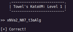
This decryption function was called twice using the recovered key, one time for each pair of inputs. After mapping the double words to ASCII encoded bytes, the correct input is revealed: xNVa2_N07_t3aAlg.
Finally, the sought after positive message is revealed.